Containing pressure within a buried Martian habitat
You may have looked, last week, at my project for a Martian base for short missions, for use by people living in the rotating stations of the areostationary orbit. On that occasion, one of my readers on LinkedIn, Jishnav Somisetty (an Indian engineer), made a remark to which I replied, but which I think deserves more attention. It concerns the containment of pressure in such an underground base, immediately below the planet’s surface.
His remark:
“2.5 m of compacted regolith at 1600 kg/m3 under 3.71 m/ss is only about 15 kpa of overburden, even a low pressure habitat at 34 kpa is pushing up harder than the soil is pushing down, you’d need something like 8 to 12 m of fill to balance 50 to 70 kpa. So the regolith is doing shielding work and the bored tunnels still have to be standalone pressure vessels anchored in tension against uplift.”
Jishnav is right. My main motivation in presenting this base model was to show how to protect the people who would stay there from radiation and micrometeorites while still giving them access to light, a minimum of comfort, and the possibility of growing a few plants (CO2 absorption, oxygen production, food, positive psychological effect in a very hostile environment). To contain the pressure, I only spoke of “insulation,” and it’s true that this was a bit short. So today I would like to “develop” the subject of compression.
Jishnav’s physics is correct. The calculation is simple: overburden pressure = ρ × g × h = 1600 × 3.71 × 2.5 ≈ 14.8 kPa, so indeed “about 15 kPa” as he says. And indeed, to balance 50 kPa with this same compacted-regolith density, you would need h = P/(ρg), i.e. about 8.4 m. I chose 50 kPa (half of Earth’s atmospheric pressure) because it is not certain that a lower pressure would be tolerable for the human body (this will also have to be tested). But on the other hand, we have a real interest in accommodating a low pressure — both on the surface of Mars and inside the orbital stations — precisely because the lower it is, the weaker the mechanical stress on the container.
NB: (1) The 8.4 m — more precisely 8.42 m — is the exact equilibrium point (zero net force) for a pressure of 50 kPa. This is also a theoretical point, since of course the thickness depends on the density of the soil, and therefore on its composition. (2) Mars’s very thin atmosphere (615 pascals at datum) changes almost nothing in this height: taking it into account, the equilibrium point only drops to 8.32 m.
In the case of the surface Martian base I recommend, insulation in the strict sense remains indispensable, but it is not sufficient. It must be accompanied by a constraint on the gas contained within the envelope, to avoid excessive pressure on the ceiling of the excavated cavity. Indeed, a sealed pocket, however well designed, contains the gas but does not resist the upward push. Without some capacity to absorb this push (a self-supporting structure, or anchors in tension within the surrounding regolith/rock), the whole pocket would tend to lift and crack the overburden above it, if the latter is not heavy and cohesive enough.
What is needed is a liner that itself works as a tensioned membrane, anchored in tension into the surrounding regolith or bearing rock. The pocket/envelope keeps its useful role (gas tightness, thermal comfort), but it must be tied to an anchored load-bearing structure.
Requirements:
1. Curvature is required, not flatness. A membrane (or a network of straps) under pressure can only balance that pressure through pure tension if it has curvature: this is Laplace’s law, T = P × R for a cylinder (T ≈ tension per unit length, R = radius of curvature). The smaller R is (the more domed the shape), the less tension is needed; flat (infinite R) would require infinite tension. Concretely, this means our envelope cannot stay flush against a flat ceiling under 2.5 m of overburden: it must be given some clearance so that it can bulge into a shallow dome (or vault) once pressurized. If it comes up flat against the overburden or a rigid slab above, we fall back exactly into the initial problem — it is then the mass of the overburden that must hold, not the tension of our straps. The depth of this bulge — the rise of the dome that the envelope itself takes within the clearance it is given — is therefore not a detail: together with the pressure, it is what determines the tension to be anchored (see point 3 below).
A useful clarification: giving the envelope some clearance does not mean letting it float at random against bare rock. The excavated surface is never perfectly smooth nor perfectly conformal to the theoretical dome — asperities, edges, abrasive dust. A thin layer of compressible foam, open-cell and as low-density as possible, can be interposed between the envelope and the ceiling to absorb these local irregularities. Its role is strictly protection against abrasion and tearing, not load transfer: its uncompressed thickness should only fill the residual clearance due to rock roughness, without ever preventing the envelope from reaching its tensioned equilibrium shape. This is the opposite of a structural support — a low-stress-plateau foam crushes at near-constant load, which is precisely what prevents it from transmitting a significant thrust to the rock.
2. The tension has to end somewhere — and this is where our thick radial walls become essential. The idea of anchoring the inextensible straps into these walls (already sized to carry a load) is the right structural answer. But there is a nuance: these walls must not be designed solely to carry a vertical compressive load (the weight of the roof and the overburden they support). The envelope anchors introduce another type of stress — horizontal thrust/pull (the push of the envelope that “wants” to spread out, or the pull of the envelope that wants to rise). It will be necessary to check that the wall (and its connection to the ground/surrounding rock) can withstand both regimes simultaneously, not just vertical compression.
3. An order of magnitude to frame the problem. A first rough benchmark, just to get a sense of scale: since the envelope is not in contact with anything on the overburden side, the entirety of the internal pressure must, one way or another, be picked up by the anchors — that is, for a room of, say, 20 m² of floor area, 50,000 × 20 = 1,000,000 N, about 102 tonnes-force in total around the room’s perimeter. But this figure is only a global vertical balance: it says nothing about the actual tension each metre of wall must anchor, which depends, via Laplace’s law from point 1, on the radius of curvature R the envelope takes — and therefore on the rise (the height of the bulge) it is allowed. For a room 5 m wide, a rise of only 30 cm gives a radius of curvature of about 10 m and a linear tension T = P × R on the order of 500 kN per metre of perimeter — which is considerable, and hard to anchor cleanly. Raising the rise to 1 m drops the radius of curvature to about 3 m, and the linear tension to roughly a third of that value, i.e. on the order of 150–160 kN/m. The lesson is counter-intuitive: a “shallow” dome, which seemed like the more modest solution, is actually the most demanding case for the anchors; it is a more pronounced bulge that lightens the load the walls must carry. This remains a manageable order of magnitude — ground anchors of several tens of tonnes each are common in terrestrial tunnelling engineering — but it does mean that the rise of each room’s dome becomes a full-fledged design parameter, to be chosen according to the strength of the available anchors, rather than a mere aesthetic detail left to chance during excavation.
Details:
1. The corridor: the best geometry in the system. A corridor is a tube — precisely the easiest shape to hold in pure tension (cylinder, constant R, Laplace’s law applies directly, without the variable-curvature complications of a square room). I would run it as an independent envelope between the two radial walls that frame it, anchored at both ends into those walls, exactly like the rooms themselves.
2. The room/corridor junction. This is where it really matters. A membrane under tension does not tolerate a clean hole — the tension that used to pass through the removed fabric has to be redirected around the opening, otherwise it tears right there (the same principle as a reinforced eyelet on a tent, or a porthole on a hull: never a bare hole, always a load-transfer ring). At each junction, a rigid frame (ring or reinforced door frame) is needed to absorb the discontinuity and transfer the load into the adjacent load-bearing wall — not just into the membrane itself.
3. The doors: a choice to be made.
Submarine-style compartmentalization: each room remains an independent envelope, and each door becomes a simple airlock (a single seal, not a true double-door airlock since the atmosphere is the same on both sides) mounted on the reinforced frame. More redundancy in case of puncture, leak, or localized fire — but each door becomes a component that has to be designed and maintained.
Single envelope per group of rooms (bedrooms on one side; on the other, the bathrooms and the technical rooms — water needs — and finally the central hall): a single continuous membrane over the whole group, interior doors just for privacy, no sealed joint at every door. Sealed doors only at the boundaries between clusters and toward the central hall — this limits the number of airlocks while still keeping real compartmentalization between units.
4. The columns: The water column under the light well, and the structural pillars, pass through the pressurized volume. The standard solution in tensioned-membrane architecture is the sealed rigid collar: bolted around the column, it converts the membrane’s radial tension into circumferential compression against an already rigid, load-bearing element. The column itself needs no particular adaptation — the collar does all the work of sealing and load transfer.
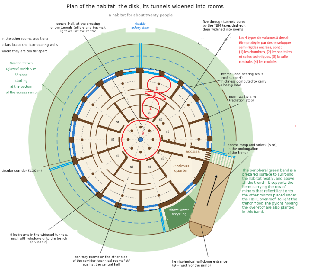
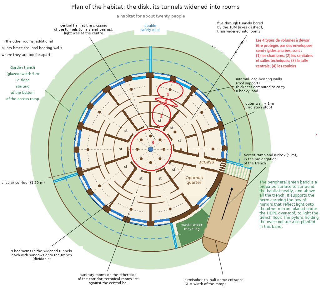
In red the 4 types of volumes that must be protected by anchored semi-rigid envelopes: (1) bedrooms, (2) sanitary facilities and technical rooms, (3) the central room, (4) corridors.
Of course, to avoid all these complications, one might consider that it would be possible to simply dig the trench deeper to obtain a much thicker galette — say 9 m, above the zero-net-force point — since this would let the sheer weight of the galette contain the internal overpressure. But besides the fact that going to such a depth would be much longer and more costly than stopping at 3 m, one has to consider that carrying such a galette would require much thicker walls, and that holding the trench walls would also become very difficult. A relatively “light” galette, sufficient to block radiation, together with a relatively shallow trench, seem clearly preferable.
We can see that what I called “insulation” is not simple, as Jishnav pointed out, and that it demands a great deal of attention, since it involves both containing pressurized gases and, as a result, containing pressure within semi-rigid envelopes. The advantage of these envelopes is precisely that, being made of materials that are partly rigid but also flexible, they can be transported in Starships without particularly difficult mass and volume constraints to manage.
We can also see that the pressure problem adds fragility to the Martian base. This fragility adds to the risk from radiation, the unbreathable atmosphere, the scarcity of water, the dust, rather weak solar lighting, insufficient gravity, the absence of any local production infrastructure, and a distance that imposes non-negligible time latency. But these difficulties are also the challenge that has to be overcome in order to live there (going down to Mars will be essential to “last” inside the orbital stations), and the satisfaction will come from the possibility of winning this challenge through mastery of the technology.
Illustrations: A Mars habitat. Credit Pierre Brisson
Copyright Pierre Brisson
To find another post in this blog which could be of interest for you, click on:
xxxx
And, if you enjoy this blog, subscribe (it’s free)!

